How to Install A Pellet Vent Pipe
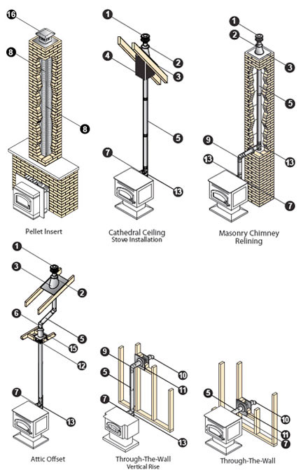
Following is a diagram of some typical pellet vent installations.

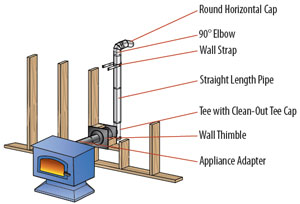
This illustration shows how to install a pellet pipe vent in these situations: pellet insert, catherdral ceiling stove installation, masonry chimney relining, attice offset, through-the-wall vertical rise and through-the-wall.
Following is the key for the parts above.
Installation Key
| 1 | Vertical Cap |
| 2 | Storm Collar |
| 3 | Flashing |
| 4 | Cathedral Ceiling Support Box |
| 5 | Straight Length Pipe |
| 6 | 45 Degree Elbow |
| 7 | Appliance Adapter |
| 8 | 60" Flexible Length |
| 9 | 90 Degree Elbow |
| 10 | Round Horizontal Cap |
| 11 | Wall Thimble |
| 12 | Ceiling Support Firestop Spacer |
| 13 | Tee w/Clean-Out Tee Cap |
| 14 | Wall Strap |
| 15 | Attic Insulation |
Typical Installations
Using the Typical Venting Installation drawings, select the appropriate component parts for your installation.
The inner pipe diameter should match the outlet size of the appliances. For installations that require 4" vent and the appliance has a 3" outlet, use an increaser adapter 3"-4".
Check the appliance manufacturer's installation instructions to confirm which types of vent configurations are permitted (i.e. horizontal, vertical, chimney reline, etc.). Also, check for any venting restrictions such as maximum horizontal run, minimum and maximum vertical rise, maximum offset, etc.
Be fire-safe! Maintain the minimum clearances (air-space) between the vent and nearby combustibles, as specified in the appliance manufacturer's installation instructions. Use proper support and bracing. Follow local building codes and have your venting system inspected.
1" clearance to combustibles in the USA for appliances using pellets, corn, or oil. 1" clearance to combustibles in Canada for oil-burning (type L vent) appliances.
3" clearance to combustibles in Canada for pellet- and corn-burning appliances.
C-UL Listed to UL 641 (MH8381 and MH14420).
ULC Listed to ULC-S609, ULC/ORD-C441 (file #CMH1439 and CMH1440).


